We lived in London for 7 years (’78 – ’86) and in my free time I took on various DIY projects and kept detailed notes on some of my projects. Now I am doing some simple plumbing in the log cabin I referred to the notes and enjoyed the memories they triggered, so I scanned the pages and after correcting scanning errors have pasted them below. I have made no changes to the words nor sought to clarify what may be unclear and have included some relevant pictures. We did not need cooling in London since the summer temps were mild, just heating for the winters and so I installed 17 hot water radiators in an older house. The total cost of components, excluding VAT which was reimbursed, was 1,440 Pounds.
Central heating installation – 1982
Introduction
Ever since I saw advertisements in ‘Exchange & Mart’ and the local newspapers for radiators, boilers and plumbing materials at discount prices, I have toyed with the idea of installing my own central heating (C.H.). Since this venture was clearly within the abilities of others, so I reasoned, then it presented a challenge all the more since I had previous little plumbing experience. The immediate problem was to find a building to C.H. At the time we were living in a small semi detached conversion.
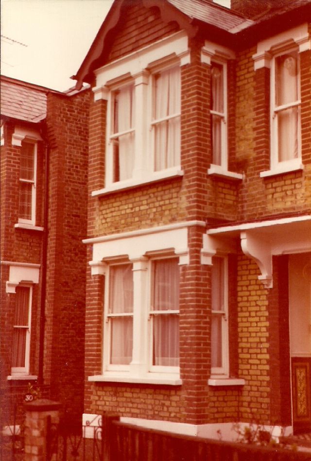
This was heated by a small internal (i.e. without a flue) gas heater which provided a small amount of heat and a large amount of condensation. More heat was provided by the owner of the freehold who lived on the ground floor and had the luxury of C.H., the heat of which rose into our flat where it tended to linger longer partly snared by the thick insulation (IOO mm) which I had installed in the loft. So we saw out two winters aided when necessary by two electric heaters and a not very efficient electric radiator. I enthusiastically studied articles and advertising literature on C.H and came to the reluctant conclusion that financially and in terms of the effort required it did not make sense to install C.H. in a small flat which was already adequately heated – I was partly influenced by the views of the ground floor occupant on the inconvenience of “major alterations” upstairs. So the idea hibernated until we moved into a large house with five bedrooms and which had no C.H. – I often wonder if I was influenced in my decision to buy the house by the fact that it had no C.H.?
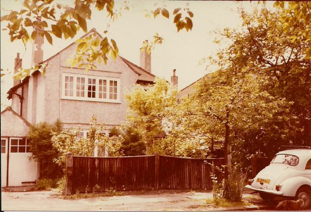
The house
The hot water was heated by an old Ideal gas domestic boiler – one inch steel pipes rose vertically from the boiler and six inches from the ceiling made a right turn and continued at a slight incline along the length and half the breadth of the room before disappearing into the ceiling from where it was a couple of feet to the rectangular zinc hot water tank. The downstairs room was always warm in summer and in winter because the hot water tank gave off heat continuously (despite my insulation attempts) and this became the cat’s favourite habitat. Also the steel pipes acted as radiators and the boiler accordingly ran intermittently.
Other heating in the house was provided by three large Electra night storage heaters (the house had a white tariff electricity meter which provided off peak electricity from I2pm to 6am at roughly half price) and two gas heaters (with flues) and an assortment of electric heaters. C.H. had to wait a full year after we moved in as I first had to rewire the whole house and insulate the loft and replace the cold water tank and attend to gutter leaks and paint the exterior etc., etc.
Eventually in Spring 1982 I was able to turn my full leisure time attention to C.H. I purchased several DIY books on C.H. and began the project.
Heating calculations
I drew a diagram of the ground floor and the first floor on vertically and horizontally lined paper taking one square to represent one foot. From the outset I adopted English measurements of feet and B.T.U.s rather than metric measurements and watts – the reason was that my main book of reference used B.T.U.s. I measured each room individually and drew its dimensions on the lined paper and the few errors which I made were quickly identified because when all the rooms had been drawn the resulting ragged outline did not coincide with the rectangular shape of the house. I performed a separate calculation for each room. Once the dimensions of the room have been measured the calculation of the B.T.U. requirement per hour is straightforward: the materials which enclose the room have varying ‘U’ values which are used in the calculation which also takes account of the desired room temperature and the number of air changes likely in the room. The thickness of the wall, whether it is cavity or solid, whether insulated or not and the temperature on the other side of the wall all affect the U value of the wall. The B.T.U.’s for all the rooms and spaces in the house are thus calculated and the total heating requirement for the house in B.T.U.’S per hour is thus derived.
A summary of the calculation is as follows:
Upstairs 42700 B.T.U.
Downstairs 47500
90200
Hot water 10000
100200
Heat loss 10200 (say 10%)
Total 110200
The upstairs heat requirement was lower than downstairs because some of the downstairs heat can be expected to rise through the ceiling and heat the upstairs although this assumption would not apply if the upstairs only is being heated. A more important reason is that the loft was insulated with IOO mm Supawrap material by myself shortly after we moved in and therefore the upstairs ceiling has a lower U value than the downstairs ceiling. Also the designed temperatures of the bedrooms which take up most of the upstairs are 60 degrees while the ground floor living rooms have designed temperatures of 65 or 70 degrees.
The heat loss of 10200 is designed to cover the boiler allowance and heat loss in pipes between the boiler and the rest of the circuit. An allowance of 15% is usually made; however I intended to lag all the pipes and felt safe in using a 10% allowance.
The heat calculations are based on the assumption that the outside temperature is 30° F i.e. it ensures that the system will be able to maintain the designed room temperatures when there is 2 deg F of frost outside. The 110,000 BTU would not be required if the temperature outside was higher than 30 deg F.
Boilers come in various sizes and I concluded that a boiler with a range of 60,000 to 80,000BTU would suffice for the following reasons:
a) it was highly unlikely that I would wish to heat the whole house at the same time. During the day we would be downstairs and only the downstairs would have to be heated although since the heat would ‘tend to rise up the stairwell if the downstairs doors were not kept closed ,the heat requirement would be higher than that calculated. Similarly in the evening only the upstairs would have to be heated.
b) Even if only the upstairs or downstairs was being heated at a time there would be a further economy in that not all the rooms on that floor would have to be heated.
c) If temperature fell to a really low temperature and the boiler could not cope then the immersion heater could heat the hot water and thus account for 10,000 BTU in the calculation. If and this is highly unlikely there is still insufficient heat then alternative sources could be employed such as the electric heaters stored in the loft. This could only occur if temperature outside was sub zero and heat was required in all the rooms at once to the designed temperatures.
The advantage in opting for a smaller boiler was that it would be able to operate continuously for longer periods than a larger boiler – this would produce operating efficiency and extend the life of the boiler since the frequent switching on and off of a boiler contributes to boiler corrosion.
The system
The next step was to decide on the components for the system:
a)Boiler –
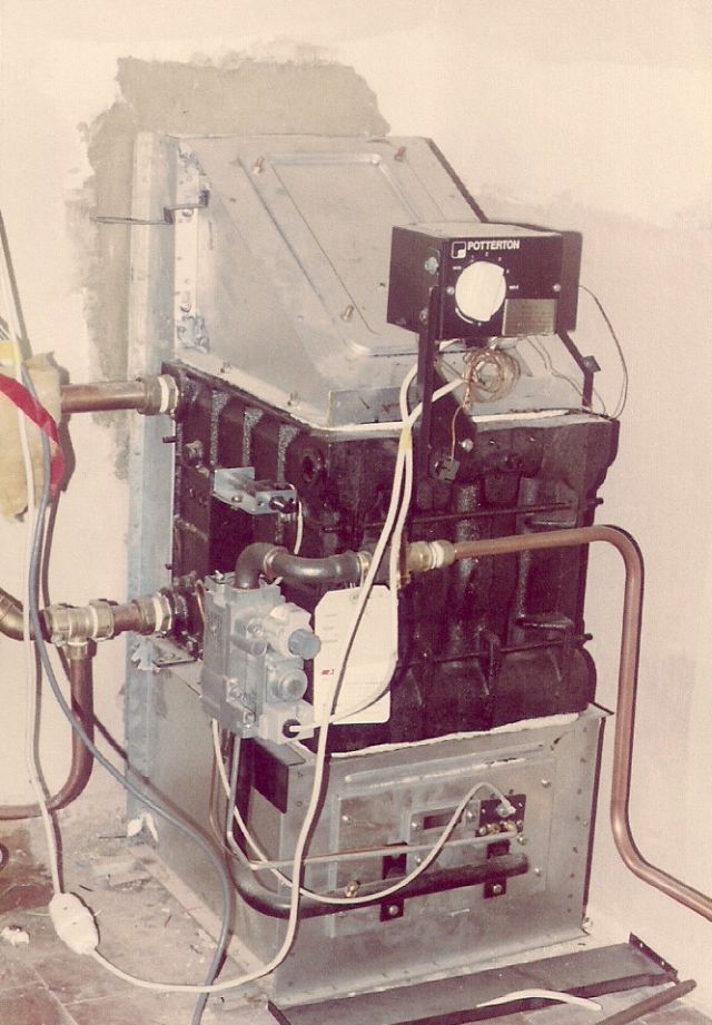
As mentioned above the boiler size was in the range 60,000 – 80,000 BTU. I decided on the Potterton make for no other reason than that most of our friends had it and recommended it. The big question was whether it should be of the balanced flue type which has an horizontal outlet or whether it should have a conventional flue. Since the boiler would be positioned in the position of the previous boiler it could make use of the existing flue. Despite the increased cost of a balanced flue of £80 we decided to opt for it – it looks neater since the outlet extends from behind it and not vertically. Another consideration is that the air is drawn from the outside through the duct and there is accordingly no need to provide for ventilation for the boiler from the air in the room.
b) Hot water tank – The chief requirement was that it should fit into the upstairs cupboard which housed the existing rectangular tank. In the event it protruded a couple of inches beyond the door and I had to insert a spacer around the door frame to enable the door to close. The cylindrical hot water tank was covered in moulded foam insulation (except for the base) and we have found this to be highly efficient. The tank is of the indirect type -this means that the water heated by the boiler travels through the tank in fully enclosed pipes and never comes into contact with the hot water which flows from the taps. The advantage of this is that chemicals can be added to the boiler circuit, which inhibit the appearance of rust, scale and various types of corrosion. Since the same water is being used continually in the heating systems the corrosion potential of the water is considerably less than if new fresh water was being continually introduced.
c) Radiators
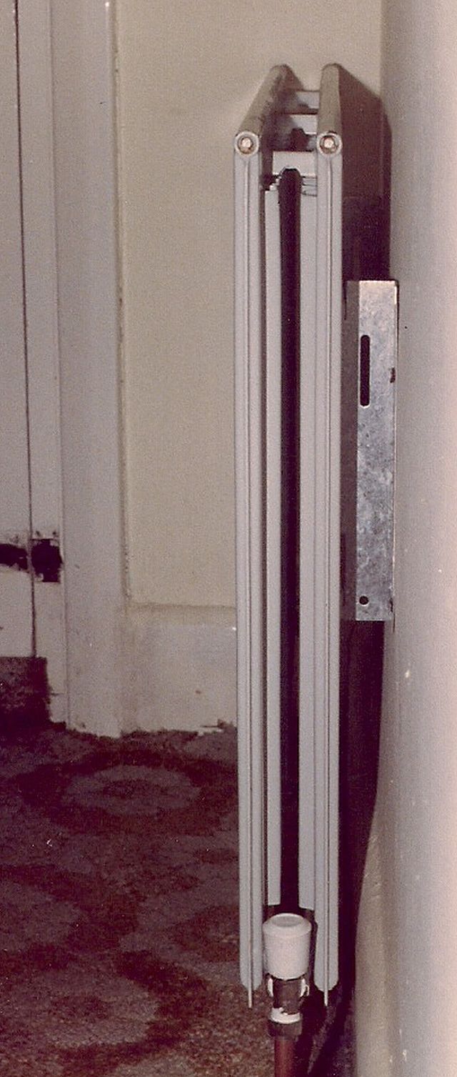
I decided on double panel convector radiators – these radiators comprise two adjacent radiator panels with a corrugated metal surface fixed in between. The corrugation boosts considerably the output. Double panels are more expensive than single panel for comparable output – however they have two advantages: they occupy a smaller wall space and since heat is lost unavoidably into the wall to which the radiator is fixed the heat loss to the wall would appear to be less since the radiator occupies a smaller wall space.
d) Other components
Pump: I chose a pump with variable output which simplifies life considerably since it is no longer necessary to calculate the ‘index circuit’ i.e. the friction in the pipes which the pump has to overcome. Pipe sizes and zone controls are discussed in the following section on the design of the system.
Design of the system
The design of the system required careful consideration since this was the first time I had installed a CH system. The position of the boiler and hot water tank were easy to decide – they merely replaced their older counterparts.
The siting of radiators is open to debate – should it, where practicable be below the windows where it could counteract the inflow of draughts and cold, should it be on an inside /internal wall or an external wall. I decided where possible to have the radiators on internal walls for the following reasons:
– a radiator below a window or an external wall meant unnecessary heat loss to the outside and it also meant that the pipework had to be longer with resulting heat loss and friction in the pipes.
– a radiator below the windows could interfere with the curtains and, if the curtains draped over the radiator, a lot of the rising heat could be lost to the window.
The chief advantage of a radiator below the window was that since we do not have double glazing, heat loss and condensation on the window can be significant. However I prefer the condensation on a window where I can notice it than on a wall where I might not.
As mentioned under heating calculations I had decided on being able to heat either half of the house at will. To do this required zone valves which are electrically operated valves inserted in the pipework which can open or close the circulation in the pipe -in all I required three such valves each with its own thermostat i.e. one for the hot water tank, one for the upstairs circuit and one for the downstairs circuit.
Pipe sizes : the size of pipes usually used in domestic installations is 15 mm, 22 mm and 28 mm. The heat carrying capacities of these pipes is-
28 mm – up to 68000 BTU per hour and 140 ft long
22 mm – up to 38000 BTU per hour and 100ft long
15 mm – up to 15000 BTU per hour and 80ft long
I prepared diagrams of the location of the radiators and using the above factors I was able to estimate what size pipe I required in various parts of the circuit.
Header tank:
Since the water in the C.H. is kept separate from the domestic hot and cold water circuits and since water expands when it is hot, there had to be provision for space into which the C.H. water could expand and this is the function of the feed and expansion tank which was to be located in the loft. The design of the feed and expansion circuit took up more time and caused more concern than any other aspect of design. The reason for this is that it is essential that the expansion pipe (which carries the expanding water and is different from the feed pipe which returns the water to the system when the water in the system has cooled and contracted) should always be unrestricted so that water can freely move through it to the F&E tank and so reduce the possibility of a pressure build up. The problem arises when the friction in the C.H. circuit is greater than the friction or pressure required to pump the water into the F&E tank. When this happens the water will then flow from the boiler to the F&E tank and back again without heating the rest of the system. There are various ways to avoid this and the location of the pump and the feed pipe and the expansion pipe in the circuit are all relevant. Perhaps the best way is to site the expansion pipe on the flow side of the boiler between the boiler and the pump. A practical problem with this arrangement is that the expansion pipe which is 22mm has to extend from the boiler all the way up to the F&E tank in the loft which means a lot more pipe and fitting is required than if the expansion pipe commenced from the hot water tank on the first floor. I adopted the latter arrangement and placed the pump on the feed side of the boiler and hoped for the best.
Pipework:
When I rewired the house I acquired in the process useful information on how the joists ran, and access positions and through laziness or foresight since I had not nailed back the floor boards lifting them and deciding on a satisfactory layout of the pipes was fairly easy.
Installation of C.H.
Installation began after weeks of deliberation and after I had bought some of the components. As mentioned at the beginning; large discounts are given by plumbing merchants and it was easy to identify merchants in the area who were offering attractive prices. Most of my requirements were made from a select group of four plumbing shops.
I had had some experience with bending springs for I5mm pipe and I decided at the outset to simplify life considerably by buying a bending machine which could bend I5mm and 22mm and cost £50.(a machine to bend the larger sizes would have cost in excess of £150).
I began with the hot water by removing the old hot water tank and replacing it with the copper pre insulated cylindrical tank. Heating was provided by the electric immersion heater prong connected by a separate way to the fuseboard with 2.5 mm cable. The circuit was switched by a double pole immersion switch with red on-light. Heating was controlled by a thermostat which slipped into the immersion heater prong. This arrangement continued for several months until the mounting electricity bill plus approaching winter compelled me with some reluctance to begin again with the installation of the C.H.
Boiler: the removal of the old boiler and the steel pipes which half circled the room was surprisingly difficult. The pipes were difficult to cut because they were in the corner where the wall met the ceiling and the boiler was heavy. This achieved the next step was to cut a hole through the wall for the balanced flue duct which proceeded relatively easily once the location of the bricks had been identified. The new boiler which was heavier than the old one was gently coaxed into position on the concrete floor in the corner.
Pipework
Pipes are more difficult to lay in the floorboards than electric cable since the pipes have to be bent whenever the direction of their path changes. This took some practice and my box full of offcuts is witness to pipes which were not bent correctly.
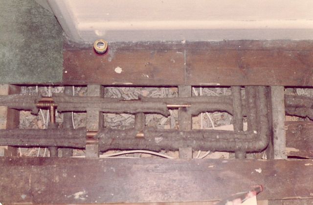
Whereas cable is run through holes at least 3 inches below the floorboards so that they are beyond the reach of floorboard nails the copper pipes are laid in notches cut at the top of the joist~ which is why the nail hammered through the floorboard to cure the squeak often produces instead a little stream .
Various techniques were developed especially to overcome the difficulty of making a pipe run beneath several floorboards and then rise vertically eight inches to reach the radiator.
Most of the joints used were presoldered capillary joints where both the fitting and the two ends of the pipe, or three ends in the case of a tee are vigorously cleaned with steel wool and then swabbed with flux and heated by butane blowtorch when the joint has been assembled. Of the three dozen joints of this type only two failed and in the one case this was due to the solder being absent from the fitting without my noticing this.
The other type of joint used was the compression joint where the olive is tightened by the compressive action of the nut on the fitting. I used boss white (it feels similar to putty) and ptfe tape. This fitting is more expensive, up to twice the price of a ‘yorkshire’ and less satisfactory since it tends to leak if not made sufficiently tight. However it has one advantage – it can easily be undone and so I used this fitting wherever I anticipated a possible future need for undoing, for example the pipes to the zone valves, boiler, hot water tank and some of the tees.
The upstairs took longer to pipe up than downstairs where I ran the pipes below the joists in the space between the downstairs floor and the concrete foundation. However the downstairs work was often done often in very restricted areas which meant a lot of wriggling and some ingenuity and needless to say there was a lot of dirt and cobwebs in the foundation.
I connected up the first floor circuit and hot water first and about a month later the ground floor circuit. There were few leaks.
Control system
The most interesting part was connecting up the wiring of the system. I used five core cable and a C.H. wiring unit which explained how every thing was to be connected. Once the logic had been grasped and with the help of my voltmeter it became quite easy. The zone valves are of the spring return type which means that their normal position is closed and when a current is applied they open and stay open for as long as the current is applied.
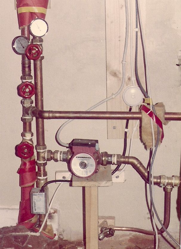
In simple terms the system works as follows:
-the programmer is set i.e. little lugs on the clock face of the programmer are arranged to go on and off at certain times in the day. The present programmer has the facility for two cycles per day and there is the facility for having either the radiator circuit or the hot water circuit or both on or off during the two cycles.
-when the cycle is reached the programmer feeds a current to the hot water or radiator thermostats; the thermostats then compare the temperature to which they have been set with the temperature in the hot water tank or room (as appropriate) .If the temperature to which they have ‘been set is higher than the temperature in their environment then heating is required and they feed a current to the zone valve. The zone valve is activated and moves from its normal closed position to the open position.
– the zone valve has a relay and once it is fully open the relay circuit is closed and a current is fed to both the pump and the boiler. Thus the pump and boiler can only be activated if at least one of the zone valves is open.
-the boiler has its own thermostat and once the temperature in the boiler reaches the thermostat setting the boiler switches off although the pump continues to run. When the water temperature falls below the boiler thermostat setting the boiler switches on again.
-when the end of the heating period is reached the programmer switches off the current to the thermostats which switch off the power to the zone valves which return to their normal closed position and in so doing they break the relay which consequently switches off the pump and boiler.
Closing comments
The system is performing to expectations.
The pump is run at its second fastest speed which is adequate to heat the house quickly. If only one of the circuits is being heated and the pump is set to speed 3 or 4 the result anticipated at the design stage occurs and the pump sends the water in a continuous circuit via the feed and expansion tank rather than the heating circuit. In fact this was happening initially when the pump was set at speed 2 but this was overcome by extending the expansion pipe about eight feet above the F&E tank in the loft.
All the pipes were lagged with slip on insulation sleeves and Fernox, a C.H. additive, was added to the water to prolong the life of the system. Both should have a beneficial effect.
The present programmer only has two cycles and cannot differentiate between the upstairs and downstairs circuits. We overcome this by manually changing the upstairs and downstairs thermostat settings so as to get heat downstairs during the evening and heat upstairs in the night. The answer is an electronic programmer which has the flexibility to cope with three distinct circuits each of which has its own time requirements. As the market develops and more houses become energy conscious I am sure reasonably priced versions will become available, one unit could then be used for switching on and off the outside light as well.
I
